Flare Stack Monitoring System
High Resolution Thermal Imaging based automatic Flare Stack Monitoring System for pilot and main flame monitoring.
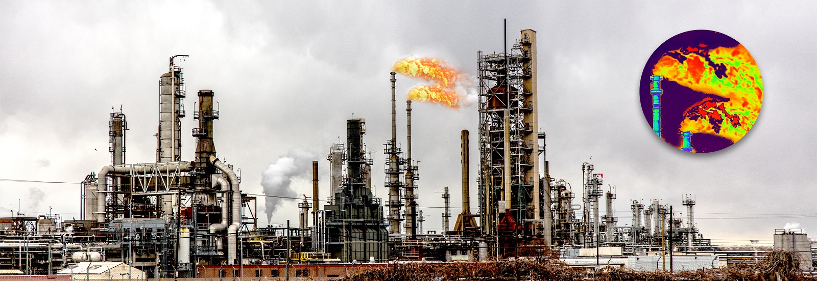
Petrochemical, Steel and some other industries generate toxic gases as their by-products which cannot be released into the atmosphere directly due to environmental and health hazards. These gases need to be burnt off before they enter the atmosphere. To do so chimneys are equipped with burners which continuously burn these toxic gases. And as this process is very critical in nature, Government and Environmental authorities regulate strict laws to continuously monitor this process and have fault detection and control mechanisms in place to ensure smooth running of the system.
There are several types of flare detection systems which are used by the industry like Thermal Imaging, Pyrometer and Thermocouples etc. The best suitable and efficient solution for flare stack monitoring is Thermal Imaging as it has the ability to monitor the flame from a distance without direct contact to the flame and Thermal Imaging gives the additional benefit of viewing the flame in the control room.
In earlier times only the detection of flame was required for this application, but recently due to enhanced safety protocols and government regulations the temperature of the flame is also measured. Some of these toxic gases are not burnt completely unless the flame is at or above a specific temperature. The Thermal Imaging system efficiently detects the main flame as well as the pilot flame and also measures the temperature of the flame continuously to ensure that the gases are completely burnt away.
In some cases additional safety features like explosion proof protection, enclosure cooling, air purging for dust accumulation can also be implemented in the same system if the user recommends the same.
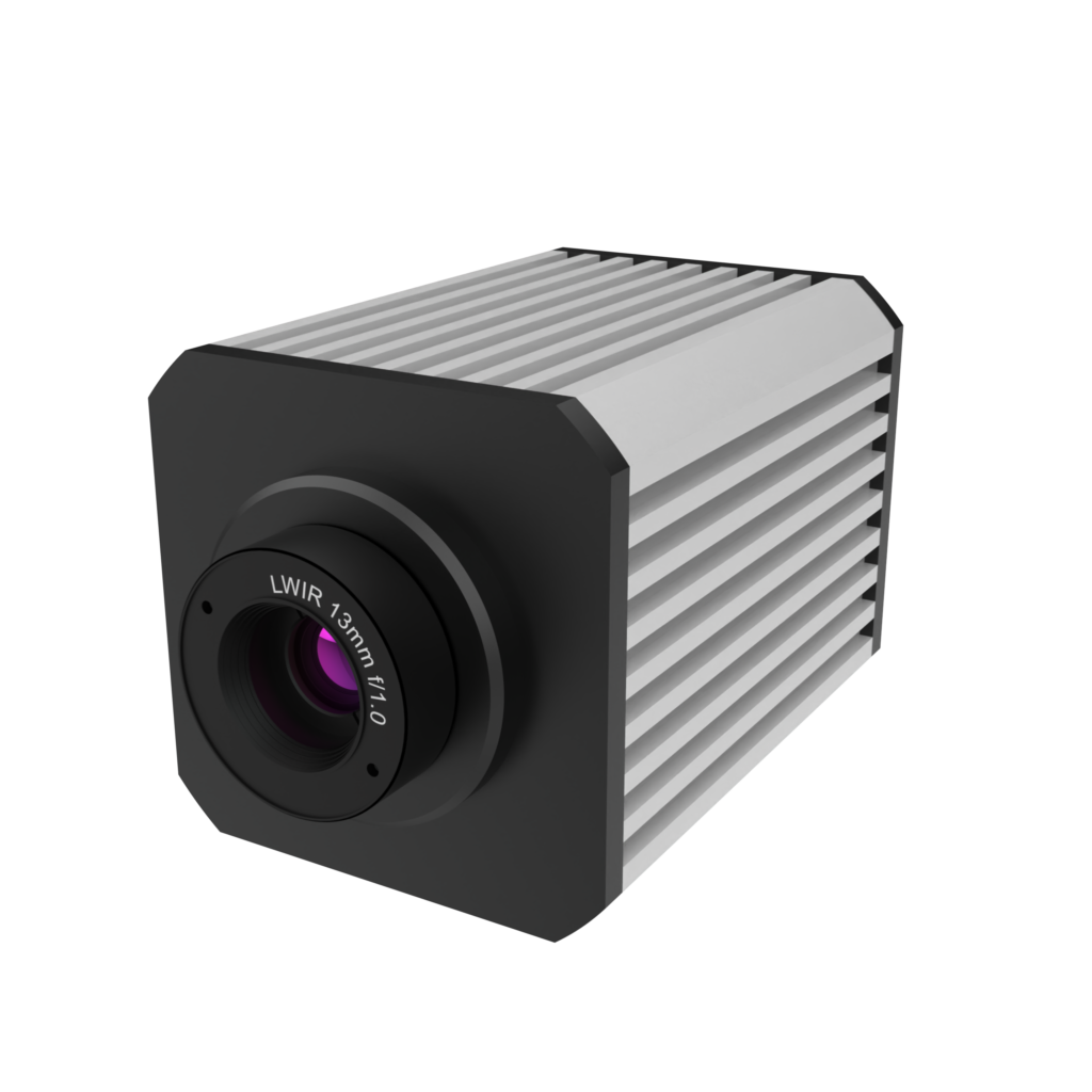
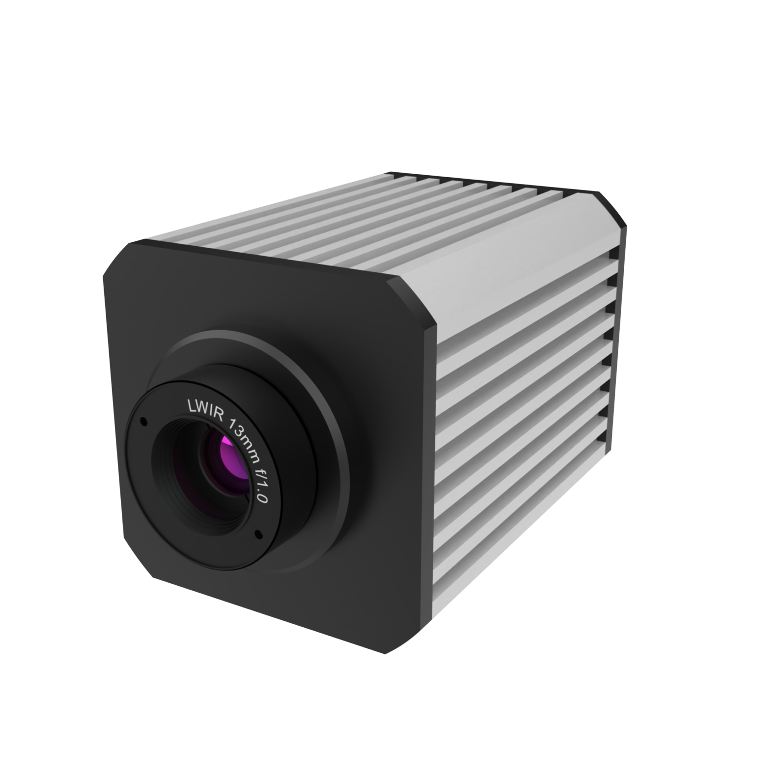
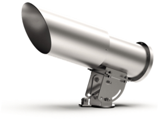
In a basic thermal Imaging flare stack monitoring system, the Thermal Imaging camera is coupled with a lens and is put inside a weather proof stainless steel/ ATEX enclosure to protect the camera from dust, rain, sunlight etc.
The camera runs on 12V DC Power which can either be supplied directly into the enclosure or suitable power adaptors can be used to convert 220/110V AC to 12V DC.
The angle of the camera then has to be adjusted using the tilting mechanism provided with the camera enclosure. The camera needs to face the flare stack directly for best results.
The camera has Gigabit Ethernet output which needs to be connected to a PC kept inside the control room or any other specified location. The Gigabit Ethernet connection can either be laid directly from camera to PC if the distance between the camera and PC is less than 100 meters. In case the distance is larger a Fiber Optic connection can be established between camera and PC.
An additional IO module can also be connected using an Ethernet switch to get Analog and digital outputs. These outputs can be triggered either when the flame is extinguished or the user can get continuous temperature reading in 4-20mA format.
In the PC the user will need to install InfraView Software for Thermal Data acquisition.
Apart from this the software also has the following features.
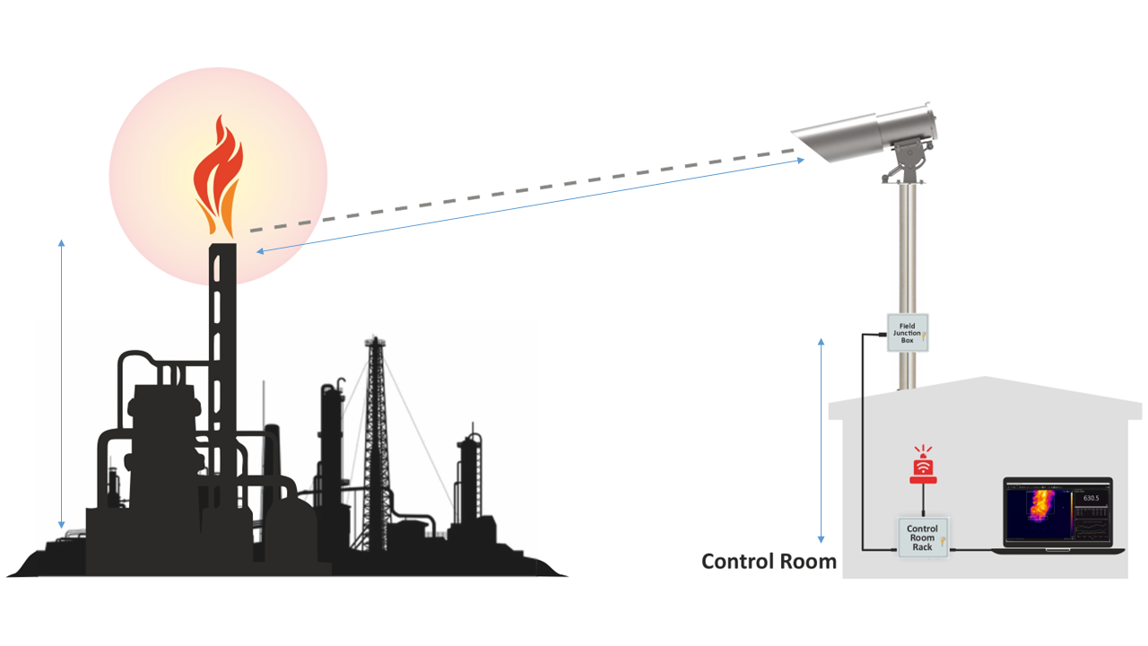
Thermal camera should be mounted on a pedestal aiming directly at the flare stack.